
The main components of LNG primarily consist of methane, ethane, propane, and a small amount of nitrogen. It is a colorless, odorless, and non-corrosive cryogenic liquid with a density lower than that of air, offering relatively high safety. As a clean energy source, it is widely used because its combustion produces almost zero sulfur dioxide and particulate emissions. However, due to its low molecular weight, low viscosity, and strong permeability, LNG is prone to leakage and diffusion. Therefore, valves used for shut-off, check, and regulation purposes in the production, transportation, and receiving processes of LNG are critical to the safe and reliable operation of the system. Currently, the shut-off valves used in key LNG equipment include gate valves, globe valves, butterfly valves, and ball valves. Ball valves are widely applied due to their simple structure, high reliability, long service life, and quick switching action, especially their advantage of low flow resistance compared to other valve types. Since LNG ball valves operate in cryogenic environments, their sealing performance is subject to high requirements. The sealing performance of ball valves is a crucial indicator of their quality; therefore, research on the sealing structures of cryogenic ball valves has always been a key focus and hotspot in this field. This paper summarizes the different types of sealing structures currently used in LNG cryogenic ball valves, analyzes the characteristics of each type, and proposes suggestions for optimization and improvement.
Different Sealing Structures of Ball Valves for LNG
The main components of a cryogenic ball valve include the seat assembly, valve body, ball, and stem assembly. The sealing structure in a ball valve mainly consists of three parts: the seal at the valve stem packing, the seal at the valve body connections, and the seal between the seat and the ball inside the valve body. To a certain extent, the sealing performance of these parts determines whether the ball valve can function properly. Normal operation of the ball valve can only be achieved when all these seals are maintained in good condition. Currently, according to the different types of sealing structures, LNG cryogenic ball valves are mainly classified into floating type, trunnion-mounted type, and orbit type.
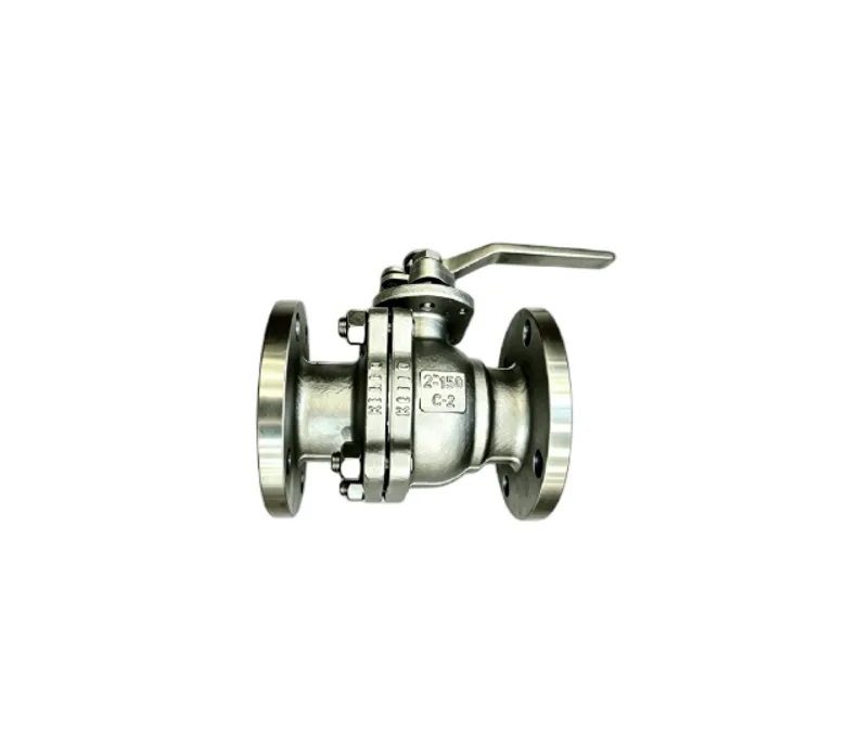
1 Sealing Structure of Floating ball Valve
The ball of a floating ball valve is clamped between two seats in a "floating" state. When the ball valve is closed, under the action of the flowing medium, the ball is pressed tightly against the sealing ring of the seat on the outlet side, thereby ensuring valve sealing.
Cao Pingfu et al. proposed that in ultra-low temperature floating ball valves, the seal at the valve stem packing area is achieved through a double seal consisting of valve stem packing and a lip-type sealing ring. First, the sealing pair formed by the lip-type sealing ring placed at the bottom of the stem packing provides the primary seal; then, the compressed valve stem packing forms the secondary seal. The disc springs placed at the bolts for compressing the packing can provide a continuous pre-tightening force. The seal between the ball and the seat is ensured by the fluid medium force, which presses the ball against the sealing surface of the seat on the outlet side. The sealing surface on the inlet side adopts a disc spring pre-loaded sealing structure, using disc springs to ensure the pressing action of the ball against the sealing surface on the outlet side. Figure 1 shows the structural configuration of its sealing parts.
Floating ball valves are mainly used under small-diameter and low-pressure operating conditions, and most of them adopt the above-mentioned elastic sealing structure. The advantage of this sealing structure is that it relies on a relatively large pre-tightening force to make the seal more reliable, while the smaller opening torque of the ball valve effectively reduces wear on the ball. However, if springs made of hard sealing materials are used for compensation, they are prone to wear, resulting in high maintenance costs. This can be improved by adopting a combined soft-hard sealing method using disc springs plus soft sealing rings, i.e., adding a sealing ring between the valve body and the seat to ensure the seal between the valve core and the seat under the action of medium force when the valve is closed, thereby reducing the displacement of the valve core. At the downstream sealing seat, the sealing reliability cannot be fully guaranteed by medium pressure alone. At the same time, due to the pressing effect of medium pressure on the sealing ring of the downstream seat, it bears a certain medium load during operation and may undergo permanent deformation. Therefore, the allowable working pressure of this sealing method cannot be too high, which limits its application in arbitrary occasions.
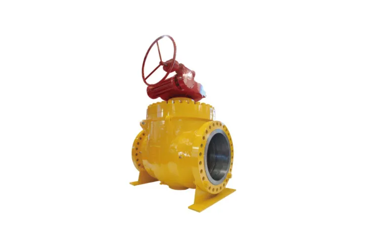
2 Sealing Structure of Trunnion-Mounted Ball Valve
Trunnion-mounted ball valves are typically used under high-pressure operating conditions or on pipelines with larger nominal diameters. Their ball is supported by upper and lower shafts, so the ball does not deviate from the axis of these shafts. The valve seats are floating and, under the action of medium pressure, are pushed toward the ball to generate sealing force for reliable sealing. Compared with floating ball valves, this design further reduces the opening and closing torque of the ball valve.
A widely used seat design for trunnion-mounted ball valves is the self-relieving seat with a single-piston effect for both the upstream and downstream seats, as shown in Figure 2. When the cavity pressure is high, the upstream seat can be pushed to relieve pressure to the upstream side. When the cavity pressure rises abnormally high, the downstream seat also plays a pressure-relieving role, simultaneously relieving pressure to the downstream flow passage. This seat design is applied in situations where sealing performance requirements are not particularly high.
An Li et al. proposed a top-entry trunnion-mounted ball valve that adopts an upstream sealing and automatic pressure-relieving seat. The upstream seat is a sealing seat with a single-piston effect. When the pipeline pressure is low, a spring is arranged on the back side of the seat to ensure sufficient initial pre-tightening force for sealing. When the pipeline pressure is high, the pressure-bearing area at the seat in the pipeline satisfies A₁ > A₂, so the upstream seat is pressed tightly against the ball under the action of medium pressure to ensure sealing. When the cavity pressure is excessively high, it can push the seat in the reverse direction to relieve pressure to the upstream side [13]. The downstream seat has a double-piston effect. Since the pressure-bearing areas at the pipeline side and the valve cavity side satisfy A₁ > A₂, A₃ < A₄, and A₁ + A₃ > A₂ + A₄, the downstream seat is always kept tightly against the ball, maintaining a good sealing state. The sealing configurations of the upstream and downstream seats are shown in Figures 3 and 4. The advantage of this structure is its excellent sealing performance, because when the valve is in operation, it can not only ensure sealing at both the upstream and downstream sides simultaneously but also perform automatic pressure relief.
Wang Fujun et al. also proposed the adoption of the above-mentioned automatic pressure-relieving seat, while simultaneously designing a multi-seal structure at the valve stem to prevent water from entering the packing during hydrostatic testing, which would otherwise affect the sealing effect. At the same time, disc springs are arranged at the bolted connections of the packing gland plate to compensate for the effects of temperature changes and ensure good sealing. The advantage of this structure is its self-relieving function. Compared with split-body ball valves, the top-entry design offers many prominent advantages. For example, when maintenance is required, the ball and seat can be easily and quickly removed simply by taking off the valve bonnet, which compensates for the inconvenience of traditional ball valves that have to be disassembled from the pipeline for maintenance once installed. The seal between the valve body and the bonnet is not oriented along the pipeline direction, so it is not affected by the medium forces in the pipeline. The valve opens and closes rapidly, ensuring safe and reliable system operation. However, since it is difficult for a seat with a double-piston effect to actually achieve its double-piston sealing function, this technical issue needs to be addressed.
Zhang Qingshuang et al. proposed a bellows-sealed top-entry trunnion-mounted ball valve, in which the sealing seat employs a threaded guide sleeve structure. The two ends of the bellows are welded to the valve seat and the threaded guide sleeve, respectively. The end face of the threaded guide sleeve is designed with two to three threaded holes, through which screws are used to adjust the displacement at the seat. This allows the ball to be conveniently placed into the valve body from the top of the valve. The actual structure is shown in Figure 5. This sealing structure effectively improves the limitations, unreliability, and internal leakage defects of the original top-entry ball valve design. However, if a single-layer bellows structure is used, its strength is insufficient and it is prone to damage; if a multi-layer structure is adopted, the cost increases accordingly. Therefore, this design has not been widely used in large quantities.
3 Sealing Compensation Structure of Orbit-Type Ball Valve
The orbit-type ball valve utilizes the cam mechanism principle to control the opening and closing of the valve, and the opening/closing process is frictionless. Therefore, most of these valves can be operated with a small handwheel, ensuring good sealing under any working conditions, especially at low temperatures, where the various components of the complex structure may undergo certain deformations [20]. Currently, orbit-type ball valves are widely used in industries such as petroleum, natural gas, and chemicals.
Wang Wanping et al. proposed a sealing compensation structure for orbit-type ball valves that can be used in ultra-low temperature conditions. In this design, the valve stem is constructed in two sections, with an elastic element arranged between the upper and lower stem sections. This elastic element compensates for the deformation of the sealing structure caused by temperature changes during operation. Its working principle is as follows: When the valve is closed, the valve core is tightly pressed against the seat under the mechanical force exerted by the stem, and at this time, the elastic element stores a certain amount of elastic energy. Under this state, when temperature changes cause variations in sealing pressure, the elastic element, driven by the stored energy, pushes the lower stem section to move, thereby compensating for the deformation caused by temperature differences and ensuring that the valve remains in a good sealing condition. When the handwheel is turned counterclockwise, the stem moves upward, and the angled plane at its bottom causes the valve core to deviate from the seat, opening the valve.
This sealing structure not only eliminates seat friction and solves the wear problem of traditional ball valve seats, but also compensates for the effects of temperature differences on sealing pressure, enabling real-time compensation. The sealing reliability is greatly improved, and the structure is simple. It can also be designed as a top-entry type, making maintenance and disassembly convenient. As a result, this design has been widely applied.
Контактное лицо: Макс. Сонг (Сун Шаньшань)
Должность: Генеральный директор
Мобильный телефон: +86 15611322632
Скажите: +86 10 89282693
Электронная почта: international@bvmc.com
Адрес: Нет. 3, Lvhai Road, город Пангечжуан, район Дасин, Пекин


Авторское право © Пекинский завод клапанов, ООО
Карта сайтаЭтот веб-сайт использует файлы cookie, чтобы обеспечить вам максимально эффективное использование нашего веб-сайта.




 Phone